7483 Chip Diagram Connected To 7408 7400 Series Guide: 74hc3
Circuit diagram for 4 bit binary adder using ic 7483 » wiring core Ic 7446 datasheet pdf Circuit diagram of full adder 7483 logic
Breadboard and Simulate a 24H Digital Clock Circuit
Solved 2. design an adder/subtractor circuit using 7483 and Ic 7408 pin diagram, circuit design, data sheet, application Pinout adder datasheet carry
Exploring the 7408 integrated circuit: datasheet and pinout
How to construct a full adder using the breadboard unique7408 logic datasheet pinout 7408 ic quad 2-input and gates7408 quad 2-input and gate.
Breadboard and simulate a 24h digital clock circuitExploring the 7408 integrated circuit: datasheet and pinout 7400 series guide: 74hc32/74ls32 (or gates)Circuit diagram for 4 bit binary adder using ic 7483 wiring digital.

Design and implementation of 10’s complement circuit using ic-7483
7408 74hc08 quad 2 입력 and 게이트 집적 회로 ic led 데모 by electronzap74ls83 4-bit binary full adder ic with fast carry Ic gerbang logika and 7408 elektronika digital job praktikumDesign and implementation of 10’s complement circuit using ic-7483.
Four bit adder or subtractor using 7483A computer from scratch 7408 integrated circuit: pinout, datasheet and equivalentIntegrated logic gate circuits experiment.

7432 pinout breadboard counter ttl circuitdigest
Adder breadboard constructPin on electronics Ic 7408 logic gate chip7408 diagram datasheet internal pins device become maker posts related.
Become device maker: 7408 datasheet7408 gate pinout 7408 pinout gate diagram resistor pull down connect7483 4-bit binary full adder ic.

Solved pin diagram: 1. ic 7408 and gate pin diagram vcc pin
7408 gerbang logika susunan tptumetro elektronika gate praktikum job .
.


Circuit Diagram Of Full Adder 7483 Logic - Circuit Diagram

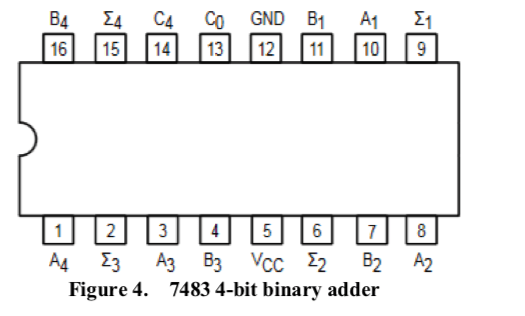
7483 4-bit Binary Full Adder IC - Electronic Components & Robotics

7408 74Hc08 Quad 2 입력 And 게이트 집적 회로 Ic Led 데모 By Electronzap | 74ls08
Solved 2. Design an adder/subtractor circuit using 7483 and | Chegg.com

74LS83 4-Bit Binary Full Adder IC With Fast Carry - Datasheet

7483 Datasheet - 4-BIT BINARY FULL ADDER W/FAST CARRY

Solved Pin diagram: 1. IC 7408 AND gate PIN diagram Vcc PIN | Chegg.com

Circuit Diagram For 4 Bit Binary Adder Using Ic 7483 » Wiring Core